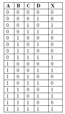
4 Input Truth Table
It is basically used to check whether the propositional expression is true or false as per the input values. For case 1 we see that an output carry is propagated when we give an input carry.
Solved Given The Following Truth Table 4 Inputs Give The Chegg Com
An LED Light-Emitting Diode provides visual indication of the gates output logic level.
. 002 Definition of a Truth Table. These truth tables can be used to deduce the logical expression for a given digital circuit and are used extensively in Boolean algebra. A truth table to show p q r p q r.
Two-input OR Gate Truth Table. OR Gate Sample Circuit Operation. Input K behaves like input R of SR flip flop which was meant to reset the flip flop.
A XNOR gate is a gate that gives a true 1 or HIGH output when all of its inputs are true or when all of its inputs are false 0 or LOW. Truth Table of NAND gate with 3 inputs Uses of NAND gate. Thus the initial state according to the truth table is as shown above.
One can design Multiplexer and demultiplexer circuits using NAND gates. On analyzing the truth table we see that the Carry is 1 when. The AND gate is a basic digital logic gate that implements logical conjunction from mathematical logic AND gate behaves according to the truth table above.
Thus for different input at D the corresponding output can be seen through LED Q and Q. The fifth column gives the truth values of p q r and the seventh column gives. A truth table is a mathematical table used in logicspecifically in connection with Boolean algebra boolean functions and propositional calculuswhich sets out the functional values of logical expressions on each of their functional arguments that is for each combination of values taken by their logical variables.
Truth table is a table that gives output for all possible combinations of inputs to a logic circuit. It is common to create the table so that the input combinations produce an unsigned binary up-count. Implement this state machine.
It consists of columns for one or more input values says P and Q and one. What is a Truth Table. Create circuit from truth table.
Let us now consider two new variables Carry Generate Gi and Carry Propagate Pi. If not all inputs to the AND gate are HIGH LOW output results. The above article on AND GATE is intended to guide students with relevant information.
These operations comprise boolean algebra or boolean functions. Construction of JK Flip Flop- There are following two methods for constructing a JK flip flop-. This is based on boolean algebra.
When the input state R 0 and S 0 is an invalid condition and must be avoided because this will give both outputs Q and Ǭ at logic level 1 at the same. A truth table has one column for each input variable commonly represented. The following is the state transition table for a Moore state machine with one input one output and four states.
The pins CLK CL D and PR are normally pulled down in initial state as shown below. In particular truth tables can be used to show whether a. Both A and B have the value 1.
TTL Logic AND Gate- 74LS08 Quad 2-input 74LS11 Triple 3-input and 74LS21 Dual 4-input. From the truth table it is clear that when both the inputs S 1 and R 1 the outputs Q and Ǭ can be at either logic level 1 or 0 depending upon the state of the inputs. This IC is used in physics and electronics practical labs to construct basic logic gates.
A truth table is a mathematical table that lists the output of a particular digital logic circuit for all the possible combinations of its inputs. Include an asynchronous reset that resets the FSM to state A. Either the value of A or B is one as well as Cin is 1 or.
A HIGH output 1 results only if all the inputs to the AND gate are HIGH 1. There is an integrated circuit IC7400 which consists of four NAND gates. The truth table identifies all possible input combinations and the output for each.
CMOS Logic AND Gate- CD4081 Quad 2-input CD4073 Triple 3-input and CD4082 Dual 4-input. They work on the basis of boolean algebra. See truth table examples to learn about conjunction disjunction and implication truth tables.
The different types of logic gates are as follow. Input J behaves like input S of SR flip flop which was meant to set the flip flop. Truth Table of Full Adder.
The following sequence of illustrations demonstrates the OR gates function with the 2-inputs experiencing all possible logic levels. 052 Input Values. Hence default input state will be LOW across all the pins.
An XNOR gate is also called exclusive NOR gate or EXNOR gateIn a two-input XNOR gate the output is high logic 1. Check more topics of Digital Electronics here. They can accept one or more input voltages but with one output voltage.
Truth Table is used to perform logical operations in Maths. A two-input OR gates truth table looks like this.

Truth Table For Four Inputs Download Scientific Diagram

Cpu Architecture How To Tell If There Is Fault In The Truth Table Stack Overflow
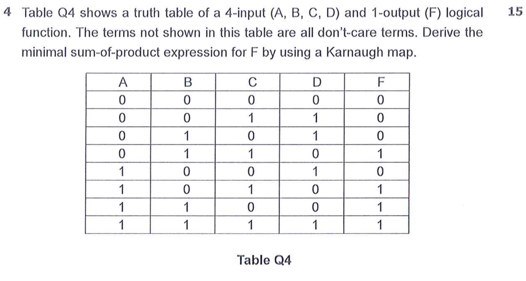
Solved 4 Table Q4 Shows A Truth Table Of A 4 Input A B C Chegg Com
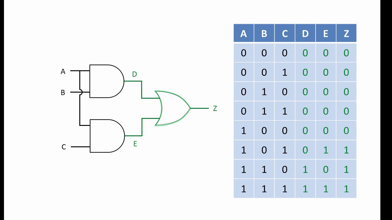
Logic Gate Combinations Youtube
No comments for "4 Input Truth Table"
Post a Comment